Search...

In low-power embedded systems, especially battery-powered devices, precise voltage sampling is critical. However, when using high-resistance voltage dividers to minimize power consumption, engineers often face unexpected ADC inaccuracies. In this article, we explain why that happens—and how to fix it.
In battery-powered products, minimizing quiescent current is essential to extend battery life. To achieve this, engineers commonly use large-value resistors in voltage divider networks for ADC (Analog-to-Digital Converter) input sampling. While this reduces power draw, it introduces a serious challenge: inaccurate voltage readings.
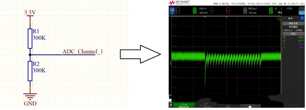
When the ADC samples a voltage from a high-impedance source (like a large-resistor divider), the internal sampling capacitor (typically around 15 pF) cannot charge quickly enough. As a result, the voltage at the moment of sampling drops temporarily, leading to glitches or under-reported ADC values.
If the resistor values are too high, the sampling capacitor pulls down the voltage briefly, and the ADC ends up reading lower than the actual voltage. This error becomes worse as resistance increases.
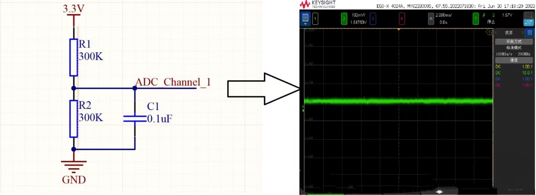
To mitigate this issue, a 0.1 μF capacitor should be added between the mid-point of the voltage divider and ground. This provides a charge reservoir that buffers the voltage drop, allowing the internal ADC capacitor to charge correctly during sampling.
Reduces sampling error significantly
Maintains low power consumption
Simple and cost-effective to implement
To ensure accuracy, the equivalent resistance seen by the ADC should comply with the formula below. This accounts for ADC clock frequency, sampling periods, and parasitic resistance:
RAIN≤fXMCLKNcycle×NN×RADC⋅CADCfXMCLK
Where:
RADC=350Ω
CADC=15pF
fXMCLK: ADC clock frequency
Ncycle: number of ADC clock cycles per sample
This technique is especially useful in:
Battery voltage monitoring
IoT sensor designs
Wearables and portable devices
Any application prioritizing low-power ADC sampling
Designing accurate ADC circuits in low-power environments doesn’t need to be complicated. By understanding the interaction between high-impedance sources and internal sampling capacitors, and applying a simple capacitor-based fix, you can achieve both low power and high precision in your voltage sampling circuits.
 More information?
AXTEK Series NYQUEST CMSEMICON ST MICROELECTRONICS Featured Manufacturers Puya MCUs ICMAN Touch Chips ZXInfoTek Holtek MCUs MORNSUN Modules
Company Profile Certificates Terms & Conditions Privacy Statement


 MCU Solutions
 PCBA Solutions
 Bluetooth Solutions
 FAQ
FAQ Contact Us
 Company News
 Technology News
 Industry News
 PCBA News
 Company Profile
 Certificates
 Terms & Conditions
 Privacy Statement
 Home Appliances
 Beauty Appliances
 Lighting
 Kid's Toys
 Security Alarm
 Health Care