Search...

The system clock frequency supports up to 48 MHz
The machine cycle is supported up to 1TSYS @FSYS≤24MHz
The fastest machine cycle supports 2TSYS @ FSYS=48MHz
Program FLASH: 16K×8Bit
Data FLASH:1K×8Bit
General RAM: 256×8Bit
Universal XRAM: 1K×8Bit
Support BOOT region, 1K/2K/4K optional
The program FLASH supports partition protection
HSI - Internal high-speed oscillation: 48MHz
HSE-External high-speed oscillation: 8MHz/16MHz
LSE-External low-speed oscillation: 32.768KHz
LSI - Internal low-speed oscillation: 125KHz
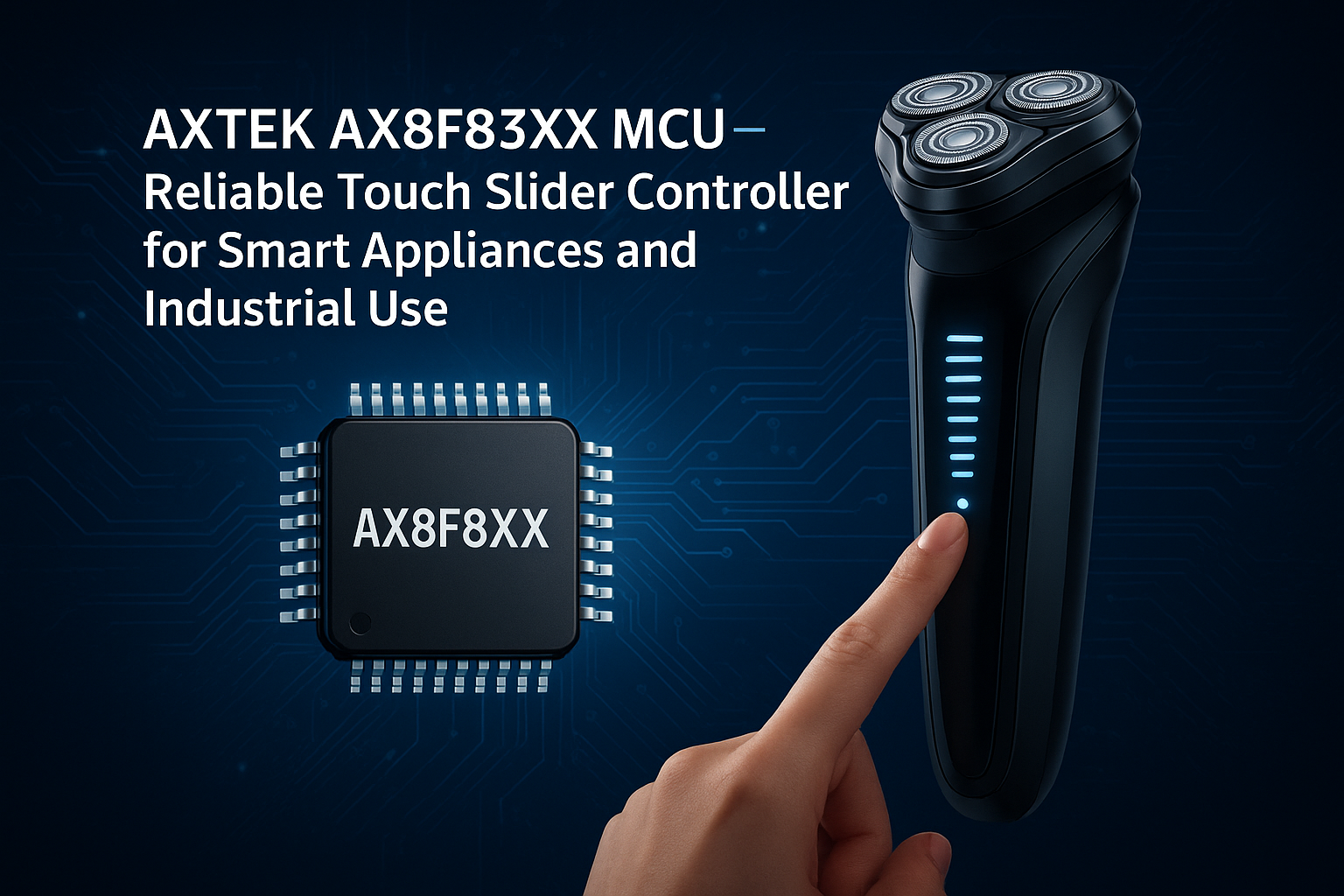
Up to 26 GPIOs
Both support pull-up/down resistor function
Both support edge (rising/falling/double-edge)interrupts
Both support wake-up function
All external port interrupts are supported
7 timer interrupts
Other peripheral interrupts
WDT Timer (Watchdog Timer)
Timer0/1,Timer2,Timer3/4
LSE_Timer (supports sleep wake-up function).
WUT (wake-up timer)
BRT (Serial Port Baud Rate Clock Generator)
CRC16(CRC16-CCITT)
50% duty cycle, frequency can be set freelyRB port
6-channel PWM
6 mutually independent cycle countersexternal
Supports independent/complementary/synchronous/grouped modes
Edge alignment is supportedexternal
Supports complementary mode dead-zone delayfunction
2.1V~5.5V
-40℃~105℃
1.8V/2.0V/2.5V/3.5V
2.0V~4.3V 8 levels selectable
Up to 26 AD external channels
Reference Voltage Selectable(1.2V/2.0V/2.4V/3.0V/VDD)
detectable Internal 1.2V reference voltagechannel
Supports hardware-triggered start conversionfeatures
Supports hardware-triggered start conversionfeatures
Duty cycle 1/4, 1/5, 1/6, 1/8 selectable
Supports two modes of common-negative/common- positive
Three clock sources are available, LSI/LSE/systemclock
COM, SEG current selectable
Supports up to 4COM x 16SEG, 5COM x 15SEG 6COM x 14SEG, 8COM x 12SEG
Three clock sources are available, LSI/LSE/systemclock
Supports both cyclic and interrupt scans
Supports each lamp display data optionally
Supports two on-time options per lamp
Current 16 gears are available
Supports up to 9 pin drives and up to 64 lamp driversChoose from dot matrix 4x4, 5x5, 6x6, 6x7, 7x7, 7x8, 8x8
Idle mode (IDLE)
Sleep Mode (STOP)
Each chip has a separate ID number
1xSPI (communication rate up to 6Mb/s)
1xI2C (communication rate up to 400Kb/s)
2xUART (baud rate up to 1Mb/s).
UART1 can be mapped arbitrarily by GPIO
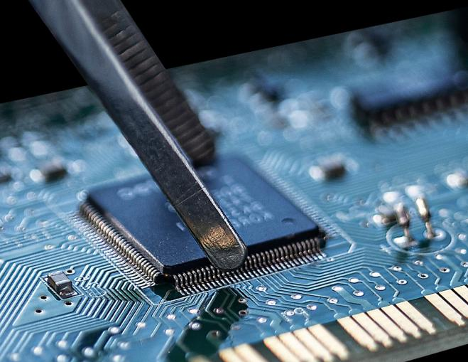
You can get your 8-Bit MCU CMS80F Series CMS80F731x solution by flling out the form below and we will contact you immediately.
AXTEK Series NYQUEST CMSEMICON ST MICROELECTRONICS Featured Manufacturers Puya MCUs ICMAN Touch Chips ZXInfoTek Holtek MCUs MORNSUN Modules
Company Profile Certificates Terms & Conditions Privacy Statement


 MCU Solutions
 PCBA Solutions
 Bluetooth Solutions
 FAQ
FAQ Contact Us
 Company News
 Technology News
 Industry News
 PCBA News
 Company Profile
 Certificates
 Terms & Conditions
 Privacy Statement
 Home Appliances
 Beauty Appliances
 Lighting
 Kid's Toys
 Security Alarm
 Health Care